
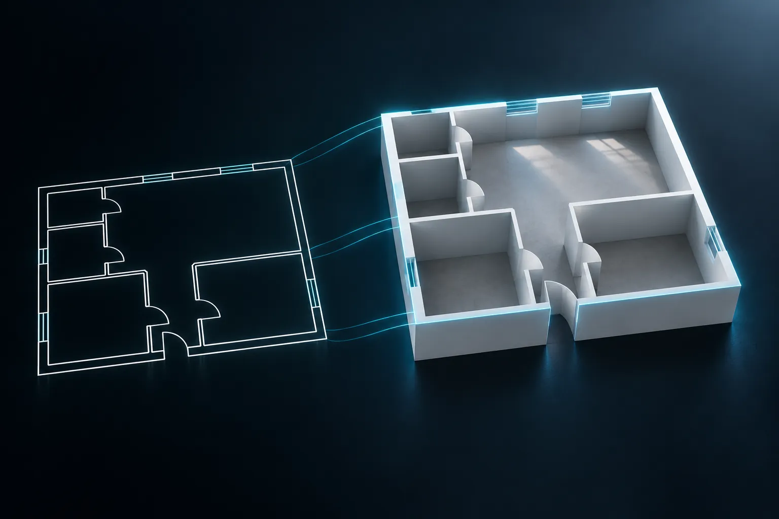
What “from 2D to 3D” really means
A 2D floor plan is a drawing seen from above: lines for the walls, arcs for the doors, numbers for the dimensions. A 3D model adds the third dimension: each wall has a height and a thickness, each opening has a width and a sill height, each room is a closed volume.
There are three levels, and it helps to know which one you need:
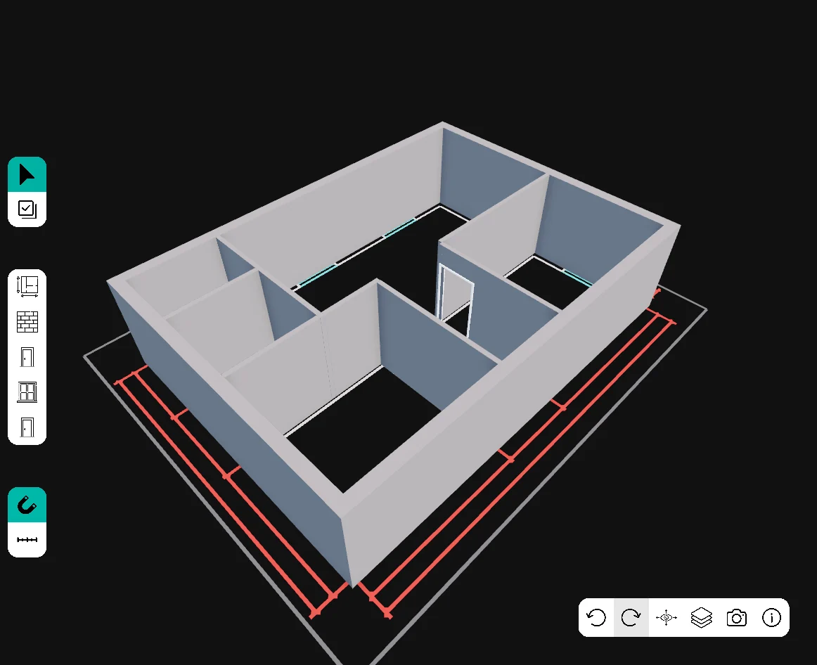
- Volumetric model: walls, openings and rooms, without materials. It is enough to understand the layout and to measure.
- Furnished model: the same volumes with floors, furniture and lights, to present an idea.
- Photorealistic render: a still image or a video calculated from the furnished model, with real lighting.
ShotPlan produces the volumetric model in the browser and calculates the quantities from it; furnished models and renders are produced on request by the Loto Studios team.
Which file to start from
The quality of the 3D depends on the starting file.
| Starting file | What it contains | What is needed to go 3D |
|---|---|---|
| DWG or DXF | Vector lines, layers, dimensions, drawing units | Nothing else: the scale is in the file and the lines guide the tracing of the walls |
| Vector PDF | Lines and texts, but without drawing units | Calibrate the scale with a known measurement, then trace the walls |
| Scan or photo | Pixels only | Calibrate the scale, trace every wall by hand, check the proportions |
If you have a choice, ask for the DWG or DXF: the DWG and DXF guide explains how to get it and what to check before importing. Today ShotPlan reads DWG and DXF Available; PDF and image recognition is Coming soon.
The four steps
- Scale. Check that one metre in the drawing is one metre in the model. If the file has no units, set the scale with two points and a known distance, for example the width of a door.
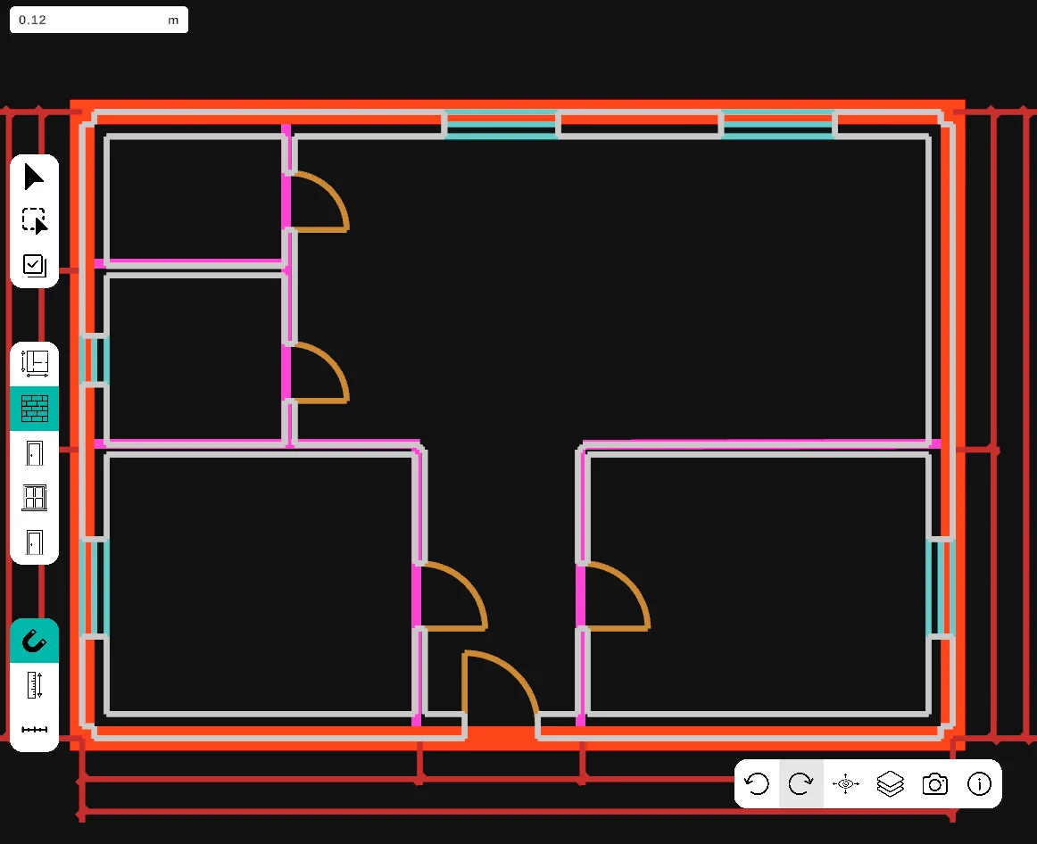
- Walls. Trace the walls following the lines of the drawing. Each wall needs a thickness (for example 30 cm outside, 12 cm inside) and a height (for example 2.70 m). With automatic snapping the cursor locks onto the ends and lines of the CAD, so the walls stay aligned.
- Openings. Place doors and windows on the walls, with width, height and sill height. Their surface is subtracted from the wall surface.
- Rooms. Close the rooms: with closed walls they can be generated automatically, otherwise you define them by hand. Every room then has a floor area and a perimeter.
At the end you switch to the 3D view and check that everything closes: no double walls, no rooms that cross a wall, heights consistent with the drawing.
The methods compared
| Method | Who traces the walls | Quantities | Control over the result |
|---|---|---|---|
| General 3D modelling program | You, from scratch | By hand or with plug-ins | Total, but it takes time and training |
| Automatic apps from a photo | The app, automatically | Often missing or approximate | Low: errors are corrected afterwards, if the app allows it |
| ShotPlan | You, on the CAD lines with snapping | Calculated from the model: floor areas, perimeters, walls, openings | High: every wall is checked while you trace it; corrections create a new revision |
The honest summary: full automation is quick on simple plans and fragile on real ones; manual modelling is precise but expensive. Tracing on a CAD base keeps the control of a person with the speed of snapping, and gives measured quantities as a result.
Mistakes to avoid
- Wrong scale. A 2% error on the scale is a 4% error on the floor areas. Always check a known measurement after import.
- Walls without thickness. A wall drawn as a single line does not give a real floor area for the rooms. Use the double line of the CAD as a guide.
- Openings on the wrong wall. A door placed outside the wall is not subtracted from any surface.
- Rooms that do not close. If two walls do not touch, the room cannot be generated: check the junctions in the 2D view.
- Forgotten heights. Set standard heights for walls, doors and windows before tracing: changing them afterwards on every wall takes time.
What you get at the end
With the model closed you have a space to look at from any angle, an image to send to the client and a list of quantities per room: floor area, perimeter, gross and net wall surface, openings. In ShotPlan these quantities are exported as a JSON file; how they become costs is explained in the quantities and costs guide.